To install front panel connectors, locate the corresponding pins on the motherboard and carefully attach each connector according to its labeled pin. Installing front panel connectors is an essential step when building a computer.
These connectors allow you to connect various devices and components to your computer’s front panel, such as the power button, USB ports, audio jacks, and more. By correctly installing these connectors, you ensure that all the front panel features work seamlessly.
We will guide you on how to install front panel connectors to your motherboard effectively. Following these steps will ensure that your computer’s front panel functions properly, allowing you to easily access various features and peripherals. So, let’s get started with the installation process.
Understanding Front Panel Connectors
What are front panel connectors?
Front panel connectors are vital components of a computer system that allows for easy access to various functions and features. They are located on the front panel of the computer case and usually consist of several small pins or sockets.
The front panel connectors serve as the interface between the computer’s motherboard and external devices such as the power button, USB ports, audio jacks, and LED indicators. These connectors enable seamless communication and interaction between the user and the computer system.
Importance of properly connecting front panel connectors
Properly connecting front panel connectors is essential to ensure the smooth operation and functionality of your computer system. Here’s why:
- Power functionality: The power button connector is responsible for turning the computer on or off. Without a proper connection, you may encounter issues like the inability to power up your system or unexpected shutdowns.
- Convenient accessibility: Correctly connecting USB and audio connectors on the front panel allows for easy access to these ports. This makes it convenient to connect USB devices, headphones, or microphones without reaching behind the computer.
- Visual feedback: The LED indicators connected to the front panel connectors provide visual feedback about the system’s status. Proper connections ensure that these indicators accurately display information like power-on status, hard drive activity, and network connectivity.
Components involved in front panel connectors
Several components play a crucial role in front panel connectors, each serving a specific purpose within the system:
| Component | Description |
|---|---|
| Power button connector | The power button connector is a small two-pin connector that connects the power button located on the front panel to the motherboard. When pressed, it sends a signal to the motherboard to initiate the power-on or power-off process. |
| Reset button connector | The reset button connector, similar to the power button connector, connects the reset button on the front panel to the motherboard. Pressing the reset button sends a signal to the motherboard, causing it to restart the computer. |
| USB headers | USB headers are connectors that provide the front panel USB ports with the necessary data and power connection. They enable the use of USB devices such as flash drives, external hard drives, and peripherals. |
| Audio header | An audio header is responsible for connecting the audio jacks on the front panel to the motherboard. It allows the use of headphones, microphones, speakers, and other audio devices without having to reach the rear audio ports. |
| LED headers | The LED headers connect the LED indicators on the front panel, such as the power LED, hard drive activity LED, and network activity LED. They provide visual feedback about the system’s status and ensure accurate display. |
Understanding the various components involved in front panel connectors is crucial for a successful installation, ensuring your computer functions properly and provides easy access to necessary features.
Preparing For Installation
Gathering necessary tools and materials
Before getting started with the installation of front panel connectors, it is important to gather all the necessary tools and materials. Having everything in one place will save you time and ensure a smooth installation process. Here is a list of items you will need:
- Computer case: Make sure you have the right case for your needs and that it is compatible with your motherboard.
- Screwdriver set: Having a variety of screwdrivers will come in handy during the installation.
- Front panel connectors: These are usually included with your motherboard or can be purchased separately.
- Documentation: Keep the user manual of your computer case and motherboard handy, as they will provide valuable information during the installation process.
- Antistatic wrist strap: This will help protect your components from electrostatic discharge while handling them.
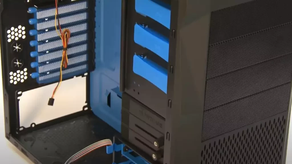
Preparing the computer case for installation
Once you have gathered all the necessary tools and materials, it is time to prepare the computer case for the installation of front panel connectors. Follow these steps:
- Place the computer case on a clean and sturdy surface, preferably on a non-carpeted area, to prevent any static electricity buildup.
- Remove the side panel of the case by unscrewing the screws on the back.
- Check the inside of the case for any pre-installed standoffs. Standoffs are small metal studs that elevate the motherboard and prevent it from touching the case directly. If there are any standoffs already installed, make sure they align with the mounting holes on your motherboard.
- If there are no standoffs or if they are not properly aligned, refer to your case’s manual for instructions on how to install or adjust them.
- Place the motherboard in the case, aligning the mounting holes with the standoffs. Use the appropriate screws to secure the motherboard in place.
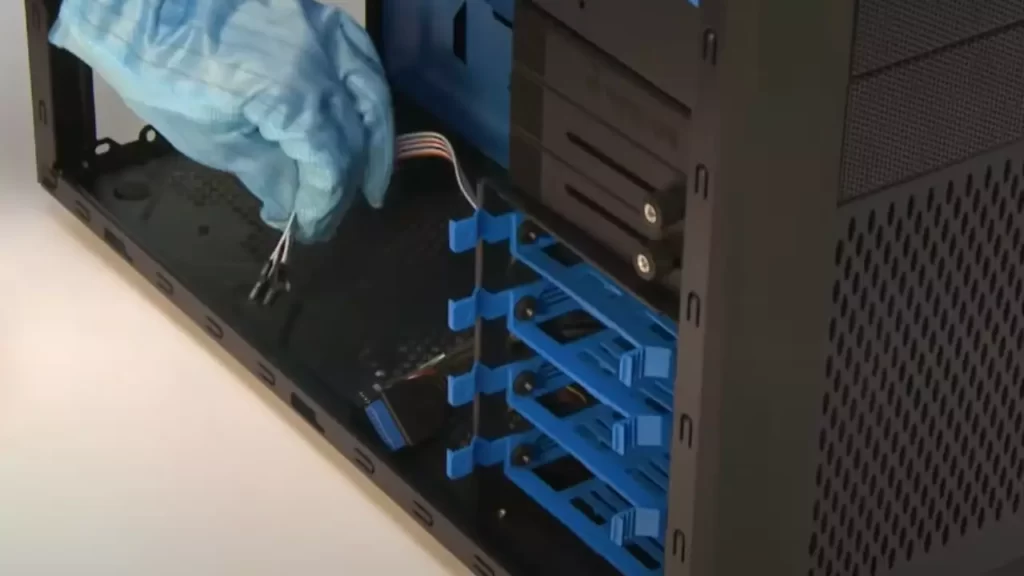
Identifying the front panel connectors
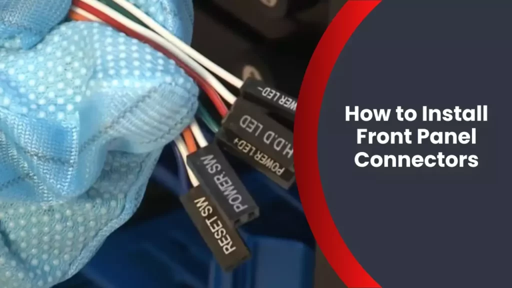
Before connecting the front panel connectors, it is essential to identify them. These connectors are located on the front panel of the computer case and are responsible for connecting buttons, LEDs, and other features to the motherboard. Here’s how you can spot them:
| Connector | Description |
|---|---|
| Power SW | This connector powers on and powers off the computer. |
| Reset SW | Pressing the reset button on the front panel will initiate a system restart. |
| Power LED | This connector controls the power LED light on the front panel, indicating whether the computer is powered on or in sleep mode. |
| Hard Drive LED | When the hard drive is being accessed, this connector lights up to show activity. |
| USB connectors | These connectors allow you to connect USB devices to the front panel. |
By familiarizing yourself with these connectors, you will have a clearer understanding of where each connection needs to be made on the motherboard. This will help you complete the installation process efficiently and avoid any confusion.
Now that you have gathered the necessary tools and materials, prepared the computer case, and identified the front panel connectors, you are ready to move on to the next step in the installation process. Stay tuned for our next section on how to connect the front panel connectors to the motherboard.
Step-By-Step Installation Process
Step 1: Connecting the Power Button and Reset Button
Start by locating the power button and reset button connectors on your motherboard. These connectors are usually labeled for easy identification.
Here’s how you connect them:
- Take the power button connector and align it with the corresponding pins on the motherboard. The power button pins are typically labeled as
PWR_BTN. - Gently push the connector onto the pins, ensuring it is properly seated.
- Repeat the same process for the reset button connector, which is usually labeled as
RESET_BTN.
Step 2: Connecting the Power LED and HDD LED
The next step is to connect the power LED and HDD LED connectors. These connectors control the activity lights on your computer case.
To connect them:
- Locate the power LED and HDD LED pins on the motherboard. These pins are typically labeled as
PWR_LEDandHDD_LED. - Take the power LED connector and align it with the corresponding pins on the motherboard. The power LED connector usually consists of two or three wires, with one wire being positive (+) and the other being negative (-).
- Connect the positive wire to the positive (+) pin and the negative wire to the negative (-) pin.
- Repeat the same process for the HDD LED connector.
Step 3: Attaching the Audio Connectors
Now it’s time to attach the audio connectors. These connectors allow you to connect your front panel audio jacks to the motherboard’s audio headers, enabling you to use headphones, microphones, and other audio devices.
Follow these steps to attach the audio connectors:
- Locate the audio header on the motherboard. It is usually labeled as
HD_AUDIOor something similar. - Take the audio connector from your case and align it with the corresponding pins on the audio header. The connector may consist of multiple wires, each of which is color-coded.
- Connect each wire to its corresponding pin on the audio header, following the color-coding. Make sure the connectors are securely attached.
Step 4: Securing the Front Panel Connectors
Once you have connected all the front panel connectors, it’s important to secure them properly to avoid any loose connections or accidental disconnections.
Here’s how you can secure the front panel connectors:
- Use cable ties or zip ties to bundle the loose cables together, keeping them neat and organized.
- Gently tuck the cables away from any fans or other moving components to prevent interference.
- Make sure all the connectors are firmly attached to their respective pins.
- Double-check all connections to ensure they are secure.
By following these step-by-step instructions, you can easily install front panel connectors on your computer. Take your time and pay attention to detail to ensure a successful installation. Happy building!
Troubleshooting And Tips
Are you experiencing connectivity issues while installing front panel connectors on your computer? Don’t worry, we’ve got you covered! In this section, we will discuss common issues that may arise during the installation process, effective troubleshooting techniques to overcome connectivity problems, and helpful tips for organizing and managing front panel connectors.
Common issues when installing front panel connectors
During the installation of front panel connectors, you may encounter some common issues that can hinder connectivity. Here are a few problems you might come across:
- Loose or improperly connected cables: One of the main culprits for connectivity problems is loose or incorrectly connected cables. Ensure that all the cables are securely plugged into their corresponding ports.
- Misaligned pins: Another common issue is misalignment of pins. If the pins are not properly aligned with the corresponding motherboard headers, the connectors may not establish a proper connection.
- Incorrect polarity: Front panel connectors often have polarity markings to indicate the correct orientation. If they are not aligned correctly, it can result in connectivity issues.
- Extreme cable tension: Excessive tension on the cables can lead to disconnection or damage. Be cautious and avoid bending or stretching the cables excessively.
Troubleshooting techniques for connectivity problems
If you encounter connectivity problems while installing front panel connectors, here are some troubleshooting techniques that can help you overcome these issues:
- Double-check cable connections: Ensure that all cables are securely connected to their respective ports. Give them a gentle tug to verify the connection.
- Inspect pin alignment: Carefully examine the pins on the front panel connectors and the corresponding motherboard headers. If they appear misaligned, adjust them using a small tool like a pair of tweezers.
- Verify polarity: Check the polarity markings on the connectors and make sure they are properly aligned. Pay attention to the positive and negative symbols to avoid any polarity-related problems.
- Try different ports: If you are facing connectivity issues, try connecting the front panel connectors to different ports on the motherboard. It could be that the port itself is faulty.
- Test the cables: Use a multimeter or continuity tester to check the continuity of the cables. This will help you identify any faulty cables that could be causing the connectivity problems.
Tips for organizing and managing front panel connectors
Installing front panel connectors can be a daunting task, especially with multiple cables to manage. Here are some tips to help you organize and manage your front panel connectors more effectively:
- Label the connectors: Use small adhesive labels or colored stickers to label each connector. This will make it easier to identify and connect them correctly.
- Bundle cables together: Use twist ties or cable management clips to bundle the front panel connectors together. This will help minimize cable clutter and make the installation process more organized.
- Refer to the motherboard manual: Consult the motherboard manual to identify the correct headers for each front panel connector. This will ensure that you connect them to the appropriate ports.
- Secure cables away from moving parts: When routing the cables, make sure they are secured away from any moving parts such as fans or drives. This will prevent accidental disconnection or damage.
By following these troubleshooting techniques and tips, you can overcome connectivity issues, ensure proper installation of front panel connectors, and have a more organized setup. Happy building!
Frequently Asked Questions
Does It Matter Which Way You Plug Front Panel Connectors?
The way you plug front panel connectors does matter. It is important to follow the instructions provided by the manufacturer to ensure proper functionality. Incorrect placement can lead to issues with audio, USB ports, power buttons, and other front panel features.
How Can You Tell If A Front Panel Connector Is Positive Or Negative?
To determine if a front panel connector is positive or negative, check the connector itself. The positive wire is usually colored red and has a “+” sign, while the negative wire is colored black and has a “-” sign.
Where Do You Plug In Front Panel Cable?
To plug in the front panel cable, locate the corresponding pins on the motherboard and connect the cables accordingly. Check the motherboard manual for specific instructions on pin location and cable orientation.
Where Do I Connect My Power Led To My Motherboard?
Connect the power LED to your motherboard by locating the front panel header. Look for the symbols (+) and (-) on the header and connect the corresponding wires from the power LED. Check your motherboard’s manual for specific instructions.
Conclusion
Installing front panel connectors can be a daunting task for beginners, but with these step-by-step instructions, it becomes a breeze. Properly connecting the power switch, LED lights, and USB ports ensures that your computer functions smoothly. Remember to consult your motherboard’s manual for specific instructions.
By following this guide, you can confidently install front panel connectors and have your computer up and running in no time. Happy building!